

Education
LASER SURFACING FOR REPAIR WELDING OF TOOLS |
|
| ... ABSTRACT |
The paper generally deals with filler materials for laser surfacing employed to repair tools for die casting of non-ferrous metals, spraying of plastics, cold-working tools, and other tools. It also treats the basic principle of laser operation, major laser and welding parameters, the most suitable type of filler material, its shape, the mode of wire feed in surfacing, the type of shielding gas, and some basic properties of surfacing welds. The chemical composition of the welding wire used affects the hardness of a surfacing weld, its wear resistance, and other mechanical properties. The shape and size of the welding wire, however, affect the rate of dilution of the parent metal and the filler material, the penetration depth, and the dimensions of the surfacing weld. Finally, some practical applications of laser surfacing to repair of tools and minor geometrical defects in the manufacture of new tools are indicated. |
| 1. INTRODUCTION |
The laser is a tool suitable for various industrial applications. In the field of mechanical engineering it is applied to cutting, joining, drilling, measuring, polishing, marking etc. Its most important application, however, is material cutting. Its application to welding is most often encountered in repair welding of various tools, and recently also in joining of car bodies in the automobile industry. The laser is a beam of concentrated and directed light energy oscillating with a certain frequency and wavelength. In industry, there are essentially two kinds of lasers, a solid laser and a gas laser. In laser surfacing the pulsed Nd:YAG laser giving average powers around 100 W and permitting welding with individual pulses or a series of pulses with a frequency of 1 to 50 Hz is employed most frequently. The maximum laser-beam power achieved in individual pulses is usually higher than 5 kW, which means that in surfacing, wires with a diameter of around 0.5 mm, and exceptionally of up to 0.7 mm, can be used. Such a concentrated energy permits to produce a surfaced layer of 0.3 mm in thickness in a single pass. The shape of the laser pulse exerts a major influence on the mode and rate of weld pool solidification. The paper shows some pulse shapes that can be used and their influence on the laser surfacing process and the properties of the weld. Laser surfacing can be applied to old tools to repair smaller worn surfaces, renew cutting edges, eliminate cracks, and repair minor defects on new tools accidentally occurring during the tool manufacture. |
|
| 2. LASER VERSUS ARC AS A SOURCE OF ENERGY |
In the conventional and most widely spread welding processes the electric arc is used. In the welding arc the energy of electric current will transform into heat energy to melt the parent metal and the filler material. Through the arc, electrically charged particles such as electrons, anions, cations, are conducted, and neutral particles such as atoms and molecules are conveyed. The electrically charged particles have a certain mass and form because of the dissociation of molecules and ionisation of atoms. All these processes occurring in the arc constitute a major hindrance to the electric current, which shows in a voltage drop and a strong increase in temperature. The arc power depends primarily on the intensity of the welding current conducted through the arc. The energy density, in addition to the current intensity, however, depends also on the arc shape. The arc shape, i.e., the arc cross-sectional area, can be influenced by several factors. The most important ones are the type of shielding gas used, the shape of welding nozzle, and the current frequency. The welding arc can be constricted by using a shielding gas having high heat conductivity, e.g., hydrogen, by mechanical constriction of the arc with a water-cooled nozzle or by using a high-frequency current. The strongly constricted arc is called the plasma arc, which is characteristic of plasma welding. In terms of physics, the laser beam strongly differs from the welding arc. Their common characteristic, however, is that they are both carriers, i.e., sources, of heat energy. The laser beam is high-density light. As distinguished from the arc, it does not consist of mass particles but only of energy particles. Figure 1 schematically shows the difference between the ordinary, visible light and the laser light. The laser light is coherent, which means that all the energy particles travel in the same direction, oscillate with the same frequency, and that the peaks and valleys of the waves are in harmony. This very harmony is the reason that the energy is strongly concentrated. If an energy medium (arc, plasma, or laser) shows an energy density of up to 107 W/cm2, this is called high energy density welding. The highest energy densities are attained right with the laser beam. In this case the energy at the focal point is so strongly concentrated that the laser beam can instantly evaporate any metallic material. That is why in welding the choice of the focal-point location at the workpiece and the energy density distribution at the focal point itself are highly important. The energy at the focal point most often shows the Gaussian energy distribution |
 |
Fig. 1. Schematic representation of ordinary, visible light and laser light: a – ordinary, visible light, b - laser light, 1 – light source, 2 – direction of light propagation. The major differences between the two heat sources, i.e., the laser and the arc, important for welding consist in different elements of the heat-energy carriers, the energy concentration, and additional accompanying effects, particularly the electromagnetic field surrounding the welding arc and depending on the welding current and the arc shape. The electromagnetic field, which always accompanies the current conduction and surrounds a conductor, will often deflect the arc from its ideal position in repair welding thus producing defects in the weld itself. Practically this disturbance is produced by the fact that a greater mass attracts the arc, which means that it makes welding in a narrow gap, up a vertical wall, or at the workpiece edges more difficult. In laser welding this disturbance, however, does not occur. |
| 3. APPLICATION OF THE LASER TO WELDING |
Generally speaking, in mechanical engineering the laser has been employed for very different purposes for many years now. Practically it is most often applied to thermal cutting, engraving, marking, measuring etc. In welding and surfacing, the laser technology is becoming established very slowly. There are several reasons for this situation. Firstly, the laser technology is very exacting, laser equipment is very expensive, and the energy efficiency is very low. Secondly, entrepreneurs are sceptic seeing the new technology and equipment being hard to exploit fully. In the recent years industrial lasers are being increasingly applied to laser repair welding of various kinds of tools, laser renewal of working surfaces, and laser surfacing. Manufacturers of laser devices have developed a suitable laser source and additional accessories to permit repair welding of various tools of different materials, shapes and differently heat-treated. For tool repairs the Nd:YAG laser seams to be the most suitable because the beam transmission is accomplished along an optical fibre. This permits welding in different positions at tools of different shapes. In the rough, laser devices for repair welding can be divided into three categories. Firstly, there are devices with an enclosure. In such devices a workpiece is placed in a special enclosed space containing a shielding neutral atmosphere and a laser beam. The welder can control and monitor the welding process by means of a special optical system. Secondly, there are devices designed for welding in the open air. The laser beam is situated at a movable hand with several degrees of freedom permitting programmed movements. The welding area is shielded by a flowing gas. The type of shielding gas used depends on the type of the material to be welded. Thirdly, there are devices intended for manual laser welding, similarly as in TIG welding. A laser torch is very similar to a TIG welding torch. The laser beam is transmitted to the torch via the optical fibre. During welding a welder will hold the laser torch in one hand and the filler material in the other hand. The welding speed and the wire feed rate at the welding area shall be determined by the welder on the basis of his personal experience. |
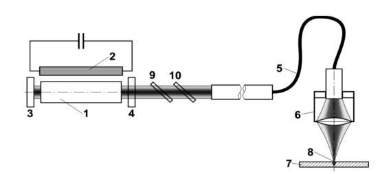 |
Fig. 2. Schematic representation of Nd:YAG laser operation: 1 – active medium emitting laser light, 2 – flashing lamp, 3 – impermeable mirror, 4 – semi-permeable mirror, 4 – optical fibre transmitting the laser beam, 6 – optical system, 7 – workpiece, 8 – beam focal-point, 9 – time sharing of beam, 10 – energy sharing of beam. The principle of the Nd:YAG laser for repair welding is shown in Fig. 2. The Nd:YAG laser (Nd - neodymium is a metal belonging to the group of lantanoids, Y - ytrrium is a rare metal, AG - aluminium garnet is a regularly crystalized aluminium oxide) is a solid laser, which means, that the laser beam will generate in the crystal structure (1) excited by the flashing lamp (2). The beam will form between the impermeable mirror (3) and the semi-permeable one (4), and be then conducted along the optical fibre (5) via the optical system (6) to the welding area (8) at the workpiece (7). More recent laser sources are equipped with devices for time (9) and energy sharing (10) of the laser beam, which considerably widens the applicability of the device. The time splitter makes it possible to release the laser beam along the first optical cable, then along the second one, and finally along the third one. The energy sharing unit, however, makes it possible to split the beam into several beams of smaller power and then use them simultaneously at several workplaces. The laser welding parameters are the laser-beam power, the focal distance, the energy density at the focal point, the position of the focal point, the laser pulse shape, the pulse frequency, and the welding speed. The most important parameters, however, are the laser-beam power, the energy density at the focal point, and the laser-beam pulse. It is with the laser pulse shape that the quality of repair welding can be considerably increased, particularly in welding of poorly weldable materials, e.g. alloyed tool steels which can get through-hardened already in air, i.e., without any additional cooling. |
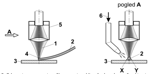 |
Fig. 3. Schematic representation of laser repair welding: 1 – laser beam, 2 – thin wire as a filler material, 3 – workpiece, 4 – position of focal point of laser beam, 5 – optical system for beam transmission, 6 – supply of shielding gas, X – area of gas overpressure, Y – area of gas underpressure and poor shielding. The principle of repair welding of tools is shown in Fig. 3. During welding the laser beam shall be positioned with its focal point at the wire. The wire shall be positioned at the area where a weld is to be made. In most cases the wire is fed to the welding area manually. The diameter of the wire used can range between 0.2 and 0.5 mm, and exceptionally up to 0.8 mm. It shall be chosen with reference to the size of the defect found at a tool and with reference to the laser-beam power. In most cases known from the practice welder's workplace is arranged for a better welder's surveillance during welding as shown in Fig. 3. This arrangement, however, is not the best as far as the protection of the welding area is concerned. The figure shows that the shielding gas is supplied to the welding area in the direction perpendicular to the longitudinal wire axis. At one side of the wire, shielding is good, at the other, however, it is somewhat poor. It would be a much better solution to supply the shielding gas in the direction parallel to the wire. For such a system, however, a special device for the supply of gas and wire would need to be designed. This means that a special, simple device could feed the wire to the welding area or that a device for automatic wire feed could be designed. In both cases, however, care should be taken to supply the gas to the welding area along the wire and to provide a gas flow as laminar as possible, i.e., with no turbulence or other disturbances. |
| 4. LASER-BEAM AND LASER-WELDING PARAMETERS |
| It has already been mentioned that the laser beam is concentrated light, i.e., concentrated energy, being most dense at the focal point and permitting heating of the filler material and the workpiece by transmitting heat from the beam to the workpiece. The most important laser-beam parameters are the focal distance, the focal-point diameter, the laser-beam power, the laser pulse energy, the laser pulse frequency, the welding speed, and the wire diameter. |
 |
Fig. 4. Optical system for the determination of laser-beam diameter at focal point: 1 – optical cable for beam transmission, 2 – fixed lens, 3 - exchangeable lens, 4 – laser-beam focal point, 5 – laser beam, 6 – workpiece; dF – laser-beam diameter at focal point at workpiece surface, FO. F – diameter of optical fibre, FL – focal distance of lens, LO – distance between the end of optical fibre and lens of the opical system, most often amounting to 80 mm. The focal distance and the beam diameter at the focal point can be varied by the optical system. Figure 4 shows a way of varying the laser-beam diameter at the focal point. The laser beam emanating from the optical fibre (1) will widen and then be focused again by the fixed lens (2) and the exchangeable lens (3). The diameter of the focal point shall thus be determined by the lens size (3) and its focal distance respectively. In repair welding with the Nd:YAG laser, lenses with focal distances F of 80, 120, 160, and 200 mm are the most often used. Thus with these lenses focal-spot diameters of 1.0, 0.8, 0.6, and 0.4 mm can be obtained. These values can be calculated using Equation 1. With more recent and expensive laser sources the focal-spot diameter can be set continuously in the range from 0.2 to 1.5 mm. By varying the focal-spot diameter, the laser-beam energy density applied to the workpiece can be varied and, consequently, the depth and width of the weld-metal area. With an increase in diameter, a wider and less deep penetration will be obtained, and with a reduction of the diameter a narrower and deeper penetration will be obtained |
The quantities used in the Equation are explained in the caption to Fig. 4. The laser-beam power is expressed in watts (W). For repair welding of tools solid lasers with powers from some ten watts to several 100 watts are used. With pulsed lasers the pulse power may be either constant throughout the pulse or vary (see Fig. 5). |
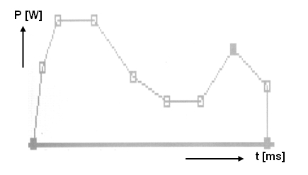 |
Fig. 5. Laser-beam pulse shape can be varied. The laser pulse shape can affect the heating process in a material and cooling of the weld pool at the welding area. In the initial pulse phase the laser-beam power in an individual pulse can increase slowly or rapidly, and then decrease slowly or rapidly. This indicates that numerous combinations are possible. Figure 5 shows a pulse divided into eight time slices. The number of the slices is different with different lasers. The laser-pulse power can thus be set at the beginning and at the end of the section. The greater the number of time sections of the laser pulse, the greater the number of optional laser pulse shapes. In tool manufacture, two types of pulses are mostly used. The first is an entirely (theoretically) square-shaped pulse which becomes somewhat distorted in practice. The second is in the shape of a distorted triangle. Both are shown in Fig, 6. In most cases the square-shaped pulse is used. With poorly weldable materials, however, the triangle-shaped energy pulse should be used. In repair welding of a cold-working tool steel with a hardness of 60 HRc for example cracks will occur in the weld if the square-shaped pulse is used. But there will be no cracks if the distorted-triangle-shaped pulse is used |
| 5. FILLER MATERIALS USED IN LASER REPAIR WELDING |
For the laser-beam repair welding process, the manual technique is usually employed. In certain cases the process can be partly automated, but it can be fully automated in very rare cases. Every repair work to be done is a unique operation requiring an individual approach to the preparation of the welding area, the choice of the filler material, and the choice of the welding parameters. When repairing larger flat, rounded or even circular workpiece configurations, the movement of the focal spot over the workpiece surface can be programmed using the latest and costlier laser devices that make welding easier and simpler and increases the productivity. In many cases, however, defects detected at tools, particularly cracks, are very small, they are located at different positions and are found at a different depth, which makes automatic movement of the focal spot over the workpiece impossible. In most cases, regardless of the programmed movement of the focal spot in repair surfacing, the filler material needs to be supplied to the area of fusion manually. For repair welding thin round wires with a diameter ranging from 0.2 to 0.5 mm and of a different chemical composition are available commercially. These are iron-base wires alloyed with different elements, of which the most important are carbon and chromium, other alloying elements being also nickel, tungsten, manganese, silicon, vanadium, titanium and some others. Studies, however, showed that the round wire was not always the best choice for surfacing operations. Figure 6 shows six differently shaped wires for laser-beam repair welding of different types of joints to be repaired. |
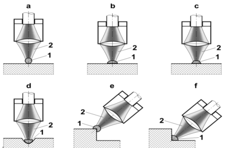 |
Fig. 6. Schematic representation of usage of differently shaped wires for laser-beam repair welding of tool parts of different configurations; 1 – welding-wire cross section, 2 – laser beam. Figure 6a shows laser welding with the round wire. The problem encountered is how to protect the weld pool after the laser beam has melted the wire and then the parent-metal surface. Figures 6b and 6d show welding with the semi-circular wire. In both cases the wire shape is adapted to the surface configuration to be repaired. The case with other wires is similar. The manufacture of the wires shown in Figs. 6c, 6d, and 6f is certainly rather exacting, but welding with such wires will considerably increase productivity, reduce the consumption of the shielding gas, and increase the quality of the surfacing welds made. The heat transfer from the beam to the wire will produce melting of a part of the wire whereas the heat conduction through the weld pool will produce melting of impurities and oxides at the tool surface. Anyway, the weld pool need to accumulate enough heat energy to form uniform grains with the parent metal. In this case the energy input is ideal. With a higher energy input, a deeper penetration and a larger heat-affected zone will be obtained. In welding, if the energy input is too high, however, spatter may occur. With a lower energy input lack of side-wall fusion will occur, which may produce weld peeling from the parent metal. Because of small wire diameters the supply of the welding wires concerned to the welding area is a very exacting operation. In most cases the wire will be supplied manually. To make the supply easier, the wire may be inserted into a thin tube, e.g. a syringe, and then positioned and fixed to the tool at the area of melting. Through the tube, however, the welding wire will be moved manually. |
| 6. SHAPES OF THE SURFACING WELDS PRODUCED WITH THE LASER |
The shape of laser surfacing welds depends on a number of factors. The major influence is exerted by the diameter and shape of the wire, and a minor one by other welding parameters. The wire diameter, however, largely determines the other welding parameters, i.e., the laser-beam power. The diameter of the focal point shall be primarily adapted to that of the welding wire. It should be equal to or twice that of the wire diameter. The laser beam should "surround" the wire and melt its entire volume. Figure 7 shows a high-quality surfacing weld. The wire diameter used was 0.5 mm and that of the focal point 1 mm. There are no undercuts visible, the dilution of the filler material and the parent metal was ideal, and there are no defects visible in the weld. If the two diameters, however, are not adapted to each other, no quality weld can be obtained. The most frequent defect occurring in this case is the lack of fusion at one or more locations in the weld. It has already been mentioned that the energy input in the wire material should be high high enough to melt also the tool surface to be surfaced. And it should be as uniform as possible over the entire cross-sectional area of the wire. Non-uniform heating of the wire will produce spatter. To obtain a high-quality surfacing weld, uniform grains need to grow between the tool surface welded and the filler material used. If this is not the case, the lack of fusion will occur that is very hard to detect after welding. |
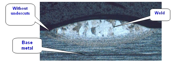 |
Fig. 7. High-quality surfacing weld showing no undercuts; the diameter of the focal point was twice that of the wire. Figure 8 shows such an unfavourable case. The diameter of the wire was too large and that of the focal point too small. The wire started melting in the centre because of the beam action, the weld pool was strongly overheated and was moving to the left and to the right side of the wire. In this case the duration of a laser pulse was relatively long. The overheated weld pool produced a quality weld to the left and to the right of the wire. In the weld centre, however, the wire could not melt uniformly because of lack of energy. If in this case the beam energy was increased or the duration of the laser pulse lengthened, the evaporation and spatter of the pool formed by the wire would occur. |
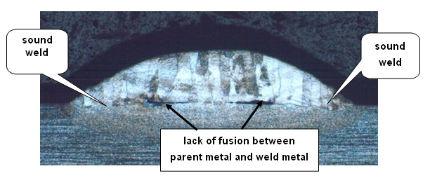 |
Fig. 8. Low-quality joint between surfacing weld and parent metal; the diameter of the wire was too large for that of the beam focal point. With such welds visual testing is always a problem because it shows a quality weld although this is not the case. Non-destructive testing methods such as ultrasonic and X-ray testing cannot detect such a defect either. This means that the welder or the operator performing the job needs to have a lot of experience and a welding turn. |
 |
Fig. 9. Low-quality joint between surfacing weld and parent metal; the diameter of the focal point was too large for that of the wire. Figure 9 shows another example of a low-quality weld. In this case the surfacing weld is good in the middle but shows lack of side-wall fusion. The focal-point diameter was namely too large and, consequently, the energy density too low. The wire melted quite well but the energy input into the wire material was too low. The molten pool formed by the wire at its sides lacked the heat energy required to form a quality joint with the parent metal. Defects may often become visible to a naked eye immediately after machining such a surfacing weld. If such a welding operation is employed to repair polished surfaces, such surfacing welds are not acceptable. |
| 7. CONCLUSIONS |
| Several conclusions may be drawn from the paper |
| :- with poorly weldable materials the laser pulse reaching its maximum power very rapidly should be employed but its power should be then decreasing slowly; |
| - the diameter of the laser-beam focal point should be larger than that of the welding wire used for surfacing, i.e., repair welding of tools; |
| - the beam focal point should be located at the wire surface; |
| - the wire shape should be adapted to the workpiece surface and the weld groove respectively; |
| - the weld shape shall be primarily determined by the size of the focal point; |
| - when the required weld size has been determined, the focal-point diameter shall be determined and the wire diameter chosen; |
| - the chemical composition of the wire shall be selected on the basis of the mechanical properties, particularly, hardness, required. |
|